
Practical ODiSI sensor installation: bonding fiber to measure structural strain
Interrogator resolution cannot compensate for poor installation. In strain measurement, the bond line transfers deformation from the structure to the fiber, so routing, substrate preparation, adhesive, protection and acceptance testing form a single system.
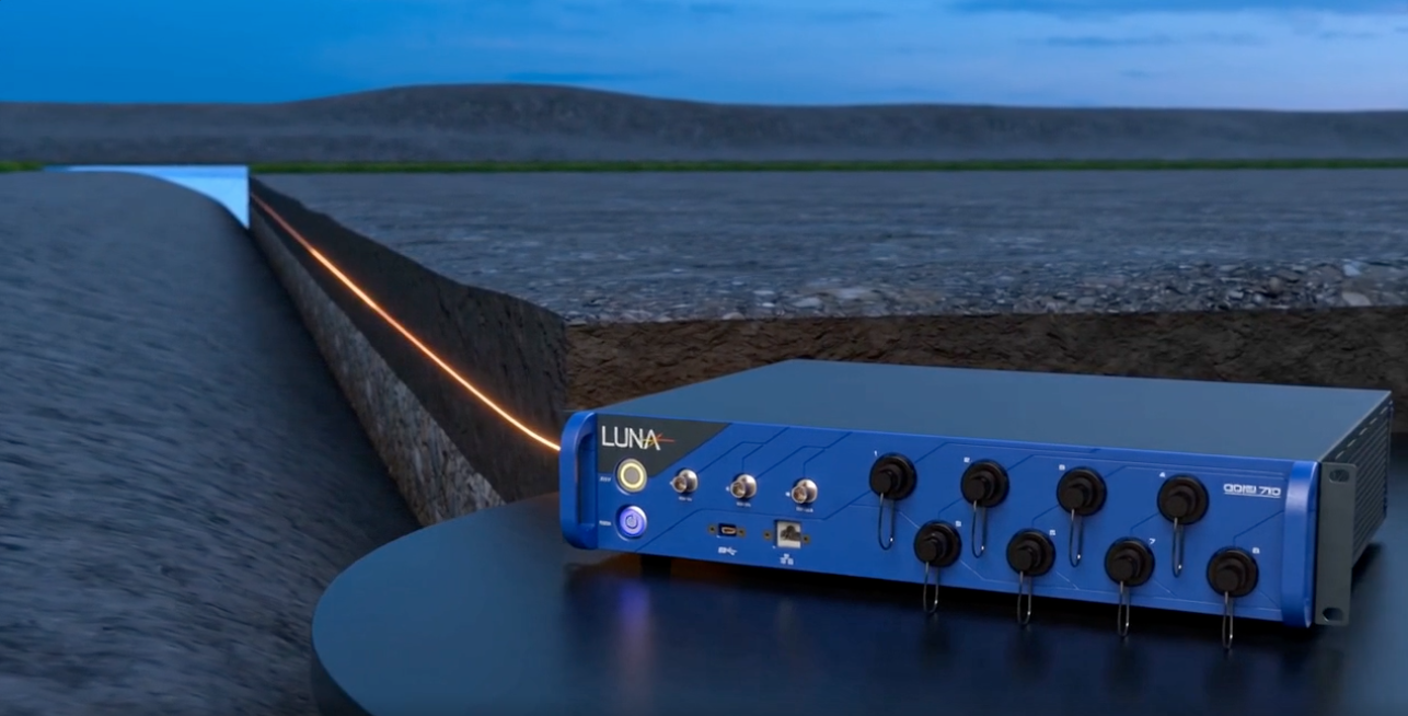
Practical ODiSI installation involves more than sticking an optical fiber in place. The aim is to build a controlled strain-transfer path from the structure, through the prepared surface and a thin adhesive layer, to the fiber.
This guide combines the capabilities of the ODiSI 7100 with Luna application instructions. The specific adhesive chemistry, substrate preparation and curing schedule must suit the material, temperature, test duration and environment.
A dense data profile, provided the fiber is properly coupled to the structure
ODiSI uses natural Rayleigh backscattering in an optical fiber. After installation, local spectral changes are converted into strain or temperature along the sensor route.
Step-by-step installation
Work through eight stages. Each ends with a quality criterion; moving on without meeting it only carries the error forward.
The bond line is the sensor’s hidden component
Move the bond-continuity slider. The model illustrates how gaps and local debonding can smooth the signal or cause dropouts. It is a qualitative illustration, not a mechanical simulation.
Transfer quality
*Educational model. Actual strain transfer depends on the substrate, geometry, adhesive material, bond thickness, temperature and load.
Select for the operating conditions, beyond the adhesive named in a tutorial
Luna’s guide uses M-Bond 200 as a quick example for short-term applications. It is not a universal recipe for composites, steel, concrete, high temperatures and tests lasting months.
| Decision | Input questions | What to qualify | Minimum evidence |
|---|---|---|---|
| Strain-transfer adhesive application-dependent | Substrate material and roughness, temperature, moisture or chemicals, test duration, strain amplitude and strain rate. | Adhesion, modulus and creep, compatibility with the fiber coating, shrinkage and curing schedule. | A trial on a representative material sample, compared with an independent measurement under load and at temperature. |
| M-Bond 200 manufacturer example | A short test at ambient temperature, rapid setup and a suitable substrate. | Surface preparation and application technique. This is a one-component cyanoacrylate adhesive, not a universal resin for every application. | A continuous bond line, no residual tack after curing and a repeatable step-load test. |
| Protective layer after the adhesive has cured | Impacts, foot traffic or tools, moisture, chemicals, transport and temperature range. | Compatibility with the strain-transfer layer, flexibility, curing, repairability and effects on thermal conditions. | A sample with the complete layer stack, with signal checks before and after exposure. |
| Lead cable and connector mechanical protection | Bend radius, part movement, fixture installation and transport of the structure. | Strain relief, cable attachment, protection of loose sections and a connector holder or bulkhead. | No cable movement transmitted to the active fiber, and a stable signal after a controlled handling check. |
Four failure patterns to recognize before the main test
The signal misses a gradient
- Check bond continuity, slack and debonding.
- Compare with a test sample or reference sensor.
- Do not try to fix a mechanical problem with a software filter.
Data loss at specific locations
- Look for abrupt strain transitions, movement of loose fiber and excessively tight bends.
- Secure unbonded sections and check the connector.
- Verify pitch/gage length and measurement range.
The profile changes without loading
- Allow the layers and structure to reach thermal equilibrium.
- Check that the compensation measurement samples the same thermal environment.
- Choose explicitly between standard HD measurement, an unbonded temperature sensor and a dedicated compensation configuration.
Disturbance near the lead or connector
- Provide cable strain relief and secure the cable outside the active route.
- Protect the fiber-to-lead transition and secure the connector in a bulkhead.
- Repeat the test after a controlled cable movement; the active profile should remain unchanged.
Test the installation method before applying it to the structure
The least costly time to detect poor strain transfer, creep or a temperature-related problem is before the main test. Run a trial on a representative material sample before installing the fiber on the target structure. Our LAB team can help select the ODiSI configuration, sensor type and trial plan, taking account of the fact that no single bonding procedure suits every structure.
Frequently asked questions
Does ODiSI fiber need to be bonded along its entire length?
For strain measurement, Luna’s guide recommends continuous bonding over the full active section. Loose sections do not transfer structural strain in a controlled way and are more exposed to movement and damage.
Can one fiber measure temperature and strain simultaneously?
Standard HD fiber is sensitive to both effects, but does not report them simultaneously as two independent quantities. Thermomechanical measurement requires a second, mechanically unbonded temperature measurement or a dedicated compensation configuration consistent with Luna documentation.
Which adhesive is best for ODiSI?
There is no single best adhesive for every substrate and environment. Luna uses M-Bond 200 as a quick, short-term example, but the choice depends on factors including material, temperature, moisture, test duration, creep and the required strain transfer.
When should the protective layer be applied?
After the strain-transfer layer has fully cured and been inspected. Protection must be chemically and thermally compatible, and its effects should be checked on a test sample with the complete layer stack.
What should an installation acceptance test include?
At minimum, a check of data continuity, route mapping, stabilization and reference recording, a small controlled load and a repeatability test after unloading. Numerical criteria should follow the test plan.
Sources and responsibilities
ODiSI 7100 parameters come from the manufacturer’s current datasheet. Luna application guides provide a starting point; adhesive chemistry and substrate preparation must be qualified for the specific application.